Planning the Skeleton
With the model finished, I moved onto rigging Tato. Planning his skeleton was the first step as it would help lay the base foundations for the deformation systems to come. (See image below).
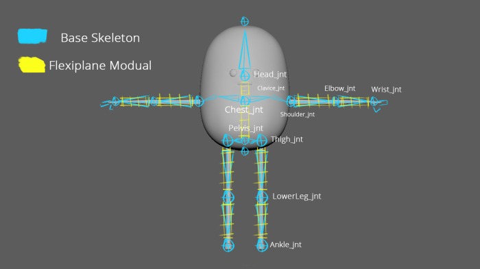
The areas marked in yellow indicate where I plan to implement the flexiplane modules to allow for exaggerated character poses. The flexiplane’s in the arms and the legs were ‘a must’ feature as it would allow our animators to achieve smear frames easily. However in the case of Tato’s body, their use would be more experimental. Based off the animatic, Tato’s only really needs to be able to bend and twist from his hips, chest and Head, so exaggerated body functions aren’t really needed and would be tricky to set up based on how limited his body mesh is. I’ll create a setup that enables the animator to turn the torso’s flexiplane functionality off and on.
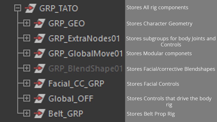
Rig Hierarchy
In order to keep my scene clean to work off, I organised and planned out my outliner.
Rigging Tato’s Body
Tato’s Body/torso was quite basic, the pelvis and chest joints were bridged using a flexiplane. A similar approach was used for how the chest was connected to the head.
The setup for connecting the flexiplanes to the pelvis and torso was relatively straight forward.
First I created two control curves, one for the pelvis and one for the torso. If I froze the transforms on either control it would reset their orientations which would mean the controls orientation would differ from the orientation of the joint they were driving which could cause problems for the animator.
To get around this, I point and orient constrained a locator to the chest/pelvis joints with the maintain offset turned off causing it to snap to the respected joint as well as taking on its orientation. Now, If I parent the control curve under the locator and freeze its transforms the result is a control curve that has adopted the orientation of the locator/joint that has a zero’d out channel box. I then used a parent constraint to connect the joint to the controller.
Finally, I used a point constraint between the chest control curve and one of the flexiplanes control curves (in this case the upper control) to drive the translate of the flexiplane and used a straight connection between the rotation attributes of the of both controls to drive the rotation as I find that straight connections evaluate quicker and are less taxing on the scene than constraints. (This process was repeated when connecting the lower flexiplane control to the pelvis joint and chest to the head).
An additional feature added to the body rig was a ‘head-follow’ attribute where you can turn the parent relationship between the chest and head off and on depending on the animators preference or task set. This was a simple setup, both the chest control and head control are children of their own locator, the head locator is then parent constrained to the chest locator. the default result is now the head control will follow the chest control, however if the animator doesn’t want the head to follow the chest they can switch the weight of the parent constraint to ‘0’. Getting to the constraint weight is a bit messy for the animator, so I created a custom attribute that does it for the animator.
Rigging Tato’s Legs
Tato’s legs consisted of a 3 layered setup:
- IK (Inverse kinematics)
- FK (Forward Kinematics)
- Bind ( With modular flexiplanes attached)
The thigh joints were aligned with the pelvis along the world Y and Z axis, this would help minimise the occurrences of buckling whenever the COG control is moved. The IK/FK joints were connected to the bind skeleton using orient constraints, (one batch of orient constraints for FK and one batch for IK) I decided to use orient constraints over a parent constraint setup as using the latter can sometimes cause skewing when the joint chain deforms as it’s trying to evaluate translation values on top of the joints rotational values.
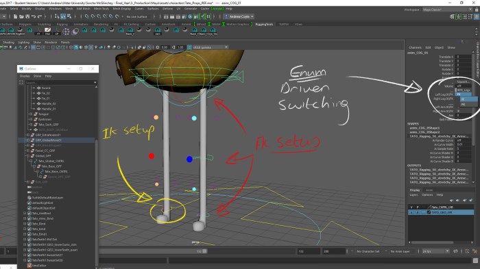
My typical process for setting up an IK/FK switch usually involves blend colour nodes and having the switching activated by ‘blend’ attribute on the blend colour. However this time I wanted to learn a different way of doing it.
I had the switching driven by the enum attributes (shown above) which were connected to the weight values of the orient constraints.
Example
Left Leg IK/FK
Enum: FK – connected to – FK Leg Orient Constraint Weight
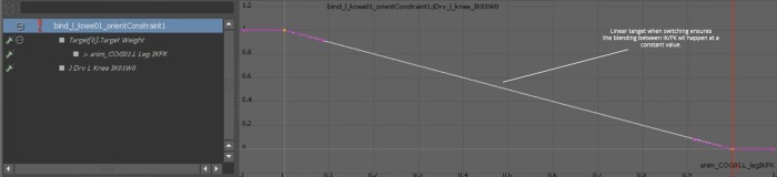
Then using Driven Keys (SDK) I set it up so that whenever the leg was in FK, the IK constraint weights would be switched to Zero with the FK constraint weights at One and vice versa. We wanted a ‘constant’ interpolation when switching so I quickly adjusted the enumerated value in the graph editor and changed its tangent to linear.
With the switching set up, I point constrained the foot joints to the end joint of my legs bind skeleton to ensure everything was working and behaving as it should.
Setting up the foot roll rig involved having a series of purposely placed locators driving the foot joints movements based off the locators pivot rotations which the animator could then drive using a series of custom attributes such as foot banking, foot roll etc.
When setting up the foot roll, it became clear that several of the locators shared differing orientations from one another which meant when I started parenting locators to locators the result will give us an offset-ed value where we’d ideally like to have clean/zeroed values for our custom attributes to drive and to avoid gimbal.
To get around this, I parent constrained a locator to each joint (maintain offset turned off) making up the foot which cause said locator to snap to it’s corresponding joint, taking on its translate and rotate values, I identified these locators as ‘Ori locs.’
Now, when parenting locators to each-other that would result in outputting offsets, I instead would parent these locators under the corresponding ‘Ori loc’ which would give a clean and zero’d out result to work with.
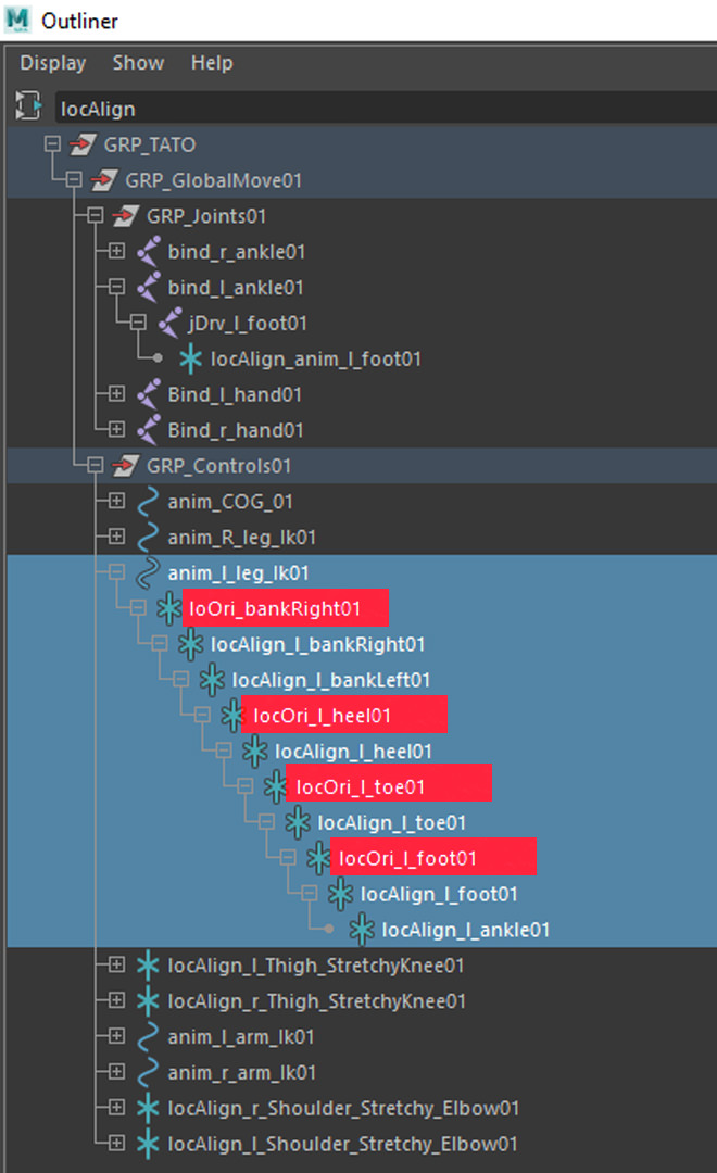
This setup was particularly useful for the functioning of the foot bank, heel,foot and toe rotations.
Additionally the legs featured custom functions such as Knee twist with volume preservation, IK/FK stretching and Bend controls for the thighs,shins and knees.
Knee Twisting
The knee twisting took advantage of the Twist attribute that the legs IK Handle was being driven by. It was a case of creating a custom floating value attribute located the the legs IK control (called Twist) and using the connection editor to connect the two together.
IK Leg Stretch
For the IK stretch, I needed to work out the resting/default length of the leg and I found this out by point constraining two locators to follow the leg. One to the Thigh FK and one to the IK leg control, as constraining to the IK leg chains would cause cycle errors on the rig.
With the locators constrained correctly I used the node editor to input their translate values into the points 1 and 2 of a distance between node to calculate the space between them.
Then to get a uniform stretch, I plugged the output of the distance node into the a divide node, where the ‘change of length’ will be divided by the ‘default/resting length‘ of the leg. Also, we need to remember to connect the scale of the global control into the legs stretch setup. I did this by taking the normalised value of the global controls scale attribute and plugging it into the input 2 of our divide node so we get an output value that’s divided by itself. Finally, I used a series of condition nodes to determine when the stretch would activate. If the default resting length was exceeded then the stretch would occur by scaling the scale X of the joint making up the leg.
The scale X attribute was also used to stretch the FK leg, where the increase or decrease of a custom attribute called length would scale the Joint inwards or outwards along that axis.
Bend Controls for the Thigh, shin and knee
Similar to how it was attached to the torso, the flexiplanes for the thigh and shin were constrained to their corresponding bind joints on the legs so they’d follow and behave as expected. However to get the knee bend function, we needed a control that followed the movement of the knee, even when it stretched and also had influence over the shin and thigh modules.
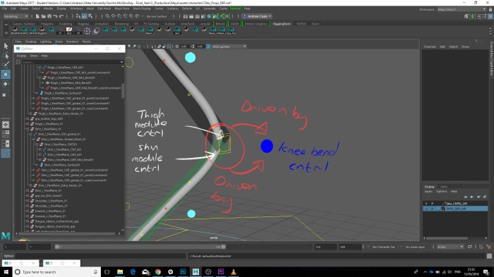
A locator was parented to the bind thigh joint which the knee control and it offset were children of. Then to ensure the control followed as the knee stretched its offset group was point constrained to the bind knee joint.
Rigging Tato’s Arms and Hands
The setup for Tato’s Arms was pretty much the same as the legs setup.
Features include:
- IK/FK Switch
- Stretchy IK/FK
- Modular flexiplane components (upper arm, fore arm and elbow)
- IK driven shoulder setup
The hand setup featured and FK driven palm control to assist the animator with achieving more poses, in addition to FK figures with additional custom attributes that drive finger bending and deformations.
This was achieved through a technique called ‘orbit joints.’ Basically, for every area that the fingure bends we have two joints.
- Fk Control driven Parent Joint
- Custom attribute driven orbit child joint
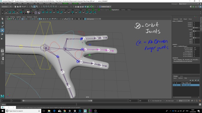
The FK driven Joint allows the animator the pose the fingers in FK however they can use the Custom attribute driven Orbit joint to add a second layer of posing or animation on the hands if needed.
With the Torso, arms and legs setup, I decided to move onto the Facial rig setup.
